| Zeile 98: | Zeile 98: | ||
== Breitband Transformator == | == Breitband Transformator == | ||
Das unten stehende Diagramm zeigt den Aufbau des 5:1 Transformators. Rechts sind die Bilder vom Transformator zu sehen den Gernot, OE1IFM aufgebaut hat. Die Ferritringe sollen dem Type 31 Material ähnlich sein und können von CPC mit der Arteikel Nummer CBBR6924 oder CBBR6945 bezogen werden. Beide Typen werden zu fünf verpackt geliefert und können über ein standard 15mm Kupfer Rohr geschoben werden. Bedauerlicherweise waren ware einige der Ferritringe etwas kleiner und haben nicht über das standard Kupfer Rohr gepasst. Wenn dieses Problem auftritt kann ein Kupferrohr aus dem Modellbau bezogen werden.<br> | Das unten stehende Diagramm zeigt den Aufbau des 5:1 Transformators. Rechts sind die Bilder vom Transformator zu sehen den Gernot, OE1IFM aufgebaut hat. Die Ferritringe sollen dem Type 31 Material ähnlich sein und können von CPC mit der Arteikel Nummer CBBR6924 oder CBBR6945 bezogen werden. Beide Typen werden zu fünf verpackt geliefert und können über ein standard 15mm Kupfer Rohr geschoben werden. Bedauerlicherweise waren ware einige der Ferritringe etwas kleiner und haben nicht über das standard Kupfer Rohr gepasst. Wenn dieses Problem auftritt kann ein Kupferrohr aus dem Modellbau bezogen werden.<br> | ||
<gallery> | |||
G8JNJ Transformator OE1IFM 01.jpg|thumb|Aufbau Transformator | |||
G8JNJ Transformator OE1IFM 02.jpg|thumb|Aufbau Transformator | |||
G8JNJ Transformator OE1IFM 03.jpg|thumb|Aufbau Transformator | |||
G8JNJ Transformator OE1IFM 04.jpg|thumb|Transformator im Gehäuse | |||
G8JNJ Transformator OE1IFM 05.jpg|thumb|Transformator im geschlossenen Gehäuse | |||
</gallery> | |||
[[Bild:G8JNJ Transformator.jpg|400px|]] | [[Bild:G8JNJ Transformator.jpg|400px|]] | ||
== How well does it work ? == | == How well does it work ? == | ||
Version vom 14. August 2009, 20:46 Uhr
Grundlagen der Breitband Kurzwellen Antenne nach Martin - G8JNJ
Übersetzung mit der freundlichen Genehmigung von G8JNJ (http://g8jnj.webs.com/)
| Wichtiger Hinweis:
Die Antenne wurde von Gernot, OE1IFM nachgebaut. Tipps und Teile stellt er gerne zur Verfügung. |
Martin, G8JNJ hat eine breitbandige vertikal Antenne entwickelt die ohne Anpassgerät auf allen Kurzwellen Bereichen von 7MHz bis 30MHz (mit eingeschränkter Leistungsfähigkeit von 3.5MHz bis 51MHz) betrieben werden kann. Bitte beachten Sie das die zu erwartende Leistungsfähigkeit der Antenne nur die eines 7m Rundstrahlers ist und nicht mit einer Yagi auf den höheren Bändern oder Lamda/2 Dipol auf den tieferen Frequenzen zu vergleichen ist.
Die beschriebene Antenne wurde nach aufwendigen Tests mit einer Comet CHA-250 mit einem speziell angefertigten 6:1 Transformator entwickelt. Es wurden viele andere Bauformen aufgegriffen und wieder verworfen bevor die unten vorgestellte Version gefunden wurde.
Impedanz des Strahler
Das Prinzip der Antenne ist das die Länge des Strahlers so gewählt wurde das der die Impedanz der Antenne auf den meisten Amateurfunk Bändern gleich ist. Ein spezieller Anpassungs- Transformator am Speisepunkt der Antenne transformiert die Fußpunkt Impedanz in die Nähe von 50 Ohm.
Die Antenne kann direkt über der Erde oder an einem isolierten Mast betrieben werden. Der Betrieb an einem Mast erhöht die Leistungsfähigkeit (darauf wird später eingegangen). Die Graphik zeigt das gemessene VSWR einer 6,5m vertikal Drahtantenne (um eine 10m Angelrute gewickelt) gegenüber einer Antenne mit 10 eingegrabenen Radials und dem unterschiedlichen Abschlusswiderständen.
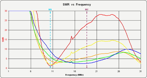
- Der rote Verlauf ist mit 50 Ohm Anschluss
- Gelb mit 100 Ohm
- Orange mit 200 Ohm
- Grün mit 300 Ohm
- Blau mit 450 Ohm
Das geringste VSWR wird mir einem Abschlusswiderstand im Bereich von 200 bis 300 Ohm erreicht.
Die zwei Marker zeigen die Lamda/4 Resonanzstelle M1 bei 10,5 MHz und die Lamda/2 Resonanzstelle M2 bei 21 MHz.
Verluste durch die Anpassung
Wenn die Verluste durch den Transformator und in etwas 2dB durch die Koaxialkabel berücksichtigt werden, das strahlende Element und die Radials gut abgestimmt werden ist es möglich ein VSWR von weniger als 2:1 (Rückflußdämpfung von 10dB) auf den meisten Amateurfunkbändern zu erreichen.
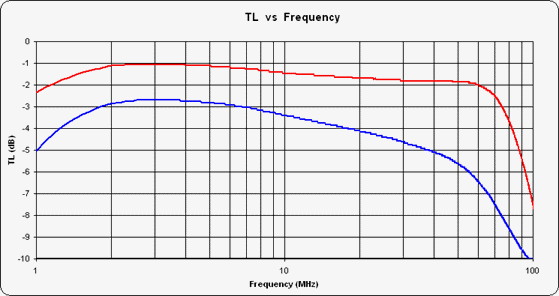
Die Graphik zeigt den Verlust des Transformators. Die blaue Line entspricht dem der Comet Nachbau und die rote Linie dem von G8JNJ entwickelten Transformator. Die Leistungsfähigkeit des neuen Transformators ist deutlich besser als die vorab getesteten. Auch wenn ein ferngesteuertes Antennenanpassgerät am Ende der verlustarmen Koaxialleitung eingeschliffen wurde waren keine Verbesserungen mehr im abgestrahlten Signal messbar. Ausgenommen waren die Frequenzen 1,9MHz und 3,6MHz wo eine Verbesserung von ca. 2dB messbar waren).
Die Durchgangsdämpfung ist deutlich geringer als die originale Version und der Aufbau der Antenne weist eine verbesserte Abstrahlungseffizienz bei geringfügig schlechterer Anpassung aus. Wie auch immer, durch die reduzierte Durchgangsdämpfung (und dem daraus beeinflussten VSWR) ist das VSWR der Antenne geringfügig höher als das VSWR der Comet Antenne.
Anpassung
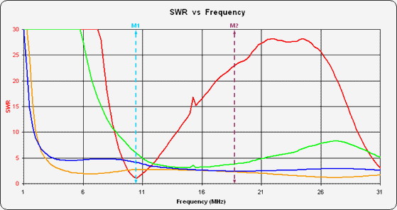
Die Graphik zeit das VSWR gemessen an der Basis eines 6,5m hohen Vertikalstrahler getragen durch eine 10m Angelrute.
- Die rote Linie zeigt die direkte Anspeisung
- Die grüne Line zeigt das VSWR mit einem 300Ohm Abschluss
- die orange Line zeigt den VSWR Verlauf mit dem Nachbau des Comet Transformators.
- die blaue Line zeigt den VSWR Verlauf mit dem von G8JNJ Transformator.
Die zwei Marker zeigen die Lamda/4 Resonanzstelle M1 bei 10,5 MHz und die Lamda/2 Resonanzstelle M2 bei 21 MHz.
Zu beachten ist das der Transformator bei den tieferen Frequenzen eine höhere Einfügedämpfung aufweist und damit das VSWR verbessert wird. Weiter Verbesserungen der Anpassung kann durch den Einsatz kurzer Radiale oder einem Gegengewicht aus Kabeln anstelle des großen Radialsystems in der Erde erzielt werden. Das verbessert den ohmschen Widerstandsanteil der Antennenimpedanz bei der niedrigsten Frequenz. Dadurch reduziert sich der Antennengewinn, der Unterschied im Gewinn der Antenne fällt auf den tieferen Frequenzen kaum ins Gewicht da die Antenne für die Frequenzen von der Konzeption her zu kurz ist und keine große Leistungsfähigkeit zu erwarten ist. Das Wissen um diese Gegebenheit darf niemanden abschrecken, viele Antennenbauformen (auch kommerzieller Fertigung) verwenden die gleiche Technologie - nur verraten sie es nicht!
Viele Leute meinen das 2 oder 3dB Verlust im Anpassungsnetzwerk zu hoch ist. Die von G8JNJ durchgeführten Tests zeigen das auch ein gutes Antennenanpassgerät eine Einfügedämpfung zwischen 0,5 und 1,5dB aufweist, und viele 4:1 Baluns, speziell die Bauform mit Windungen um Eisenpulverkerne können Einfügedämpfungen zwischen 1 und 3dB aufweisen, speziell dann wenn die Einspeisung eine niedrige Impedanz oder einen hohen Blindanteil aufweist. So sind 2 bis 3dB im Durchschnitt zu erwarten, viele Funkamateur haben diese Dämpfungswerte bereits in Ihrer Sendeleitung ohne es zu wissen, denn sie haben sich nicht die Zeit genommen um es zu messen.
Das untenstehende Diagramm zeigt das gemessene VSWR mit einem 10m langem Koaxialkabel an der Basis der Antenne. Zusätzliche Verluste in der Zuleitung verbessern das VSWR zusätzlich. Wenn ein typisches Koaxialkabel mit einer Däpfung 1 bis 2dB angeschlossen wird verbessert sich das VSWR von 3:1 auf 2,3:1 mit einer Dämpfung im Koaxialbkabel von 1dB und von 3:1 auf 1,9:1 mit einer Dampfung von 2dB im Koaxialkabel.
| Frequency | Gain | VSWR |
| 1.9 MHz | -26dBi | 8.5:1 |
| 3.6 MHz | -6dBi | 4.2:1 |
| 7.1 MHz | +1dBi | 2.1:1 |
| 10.1 MHz | +1dBi | 1.75:1 |
| 14.1 MHz | +1dBi | 1.46:1 |
| 18.1 MHz | +3dBi | 1.94:1 |
| 21.1 MHz | +4dBi | 2.25:1 |
| 24.9 MHz | +4dBi | 2.73:1 |
| 29 MHz | +2dBi | 2.38 |
| 51MHz | +1dBi | 1.5:1 |
Strahlungsdiagramm
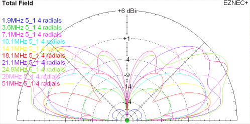
Eine bessere Bewertung der Leistungsfähigkeit kann aus dem unterstehenden Diagramm entnommen werden. Zu beachten ist das der Abstrahlungswinkel bei bei 29MHz und 51MHz ansteigt und dadurch der Gewinn geringer ausfällt.
Aufbau der Antenne
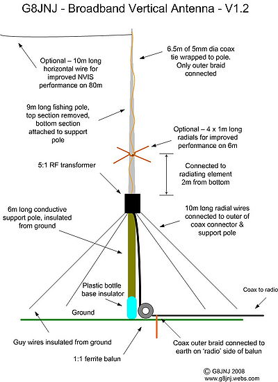
|
|
Breitband Transformator
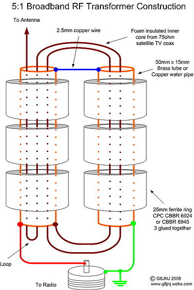
Das unten stehende Diagramm zeigt den Aufbau des 5:1 Transformators. Rechts sind die Bilder vom Transformator zu sehen den Gernot, OE1IFM aufgebaut hat. Die Ferritringe sollen dem Type 31 Material ähnlich sein und können von CPC mit der Arteikel Nummer CBBR6924 oder CBBR6945 bezogen werden. Beide Typen werden zu fünf verpackt geliefert und können über ein standard 15mm Kupfer Rohr geschoben werden. Bedauerlicherweise waren ware einige der Ferritringe etwas kleiner und haben nicht über das standard Kupfer Rohr gepasst. Wenn dieses Problem auftritt kann ein Kupferrohr aus dem Modellbau bezogen werden.
-
Aufbau Transformator
-
Aufbau Transformator
-
Aufbau Transformator
-
Transformator im Gehäuse
-
Transformator im geschlossenen Gehäuse
How well does it work ?
It depends upon what you choose to compare it against, and on which bands. For example I would expect it to perform fairly well against something like an 18AVT on the HF bands, however it will not work anything like as well as a 132ft wire on the LF bands. I estimate 8 to 10dB worse on 80m and 20 to 30 dB worse on 1.9MHz. The only fair comparison would be against the same radiator and counterpoise, but fed with an auto-tuner in place of the matching transformer, as this would represent the best performance you could achieve in this configuration. This is how I measured the antenna performance and the standard I judge it against. By its very nature the transformer version will be worse than this ideal, but I think it's worth trading a few dB of additional loss in order to obtain broadband operation.
In summary it compares favourably with other multiband vertical antennas of similar height on the HF bands but not quite as well on the LF bands.
Why can I hear stations, but they can’t hear me ?
You would expect that if you can hear stations you should be able to work them, however the lower noise floor on receive means that you can sometimes hear stations on the LF bands which would otherwise be masked by QRM on larger antennas. In summary the signal level is lower but the signal to noise ratio is much better.
You can hear DX with it, and it seems to work very well on RX, but perhaps not quite as well on TX, which seems strange as you should expect reciprocal performance. I can measure my transmitted field strength remotely and compare the antenna against other designs and it seems to match dB for dB on TX and RX (apart from obvious absolute gain differences). Yet sometimes I call stations on the vertical and they don't come back, switch over to the other antenna and they do, even though on receive they are the same strength, it's a very odd phenomenon but I suspect it's simply down to a better receive S/N ratio on the vertical (as opposed to the absolute signal strength). I find it works well as a receive antenna on 160m and one constructor John, G4IJD, has heard a ZL station on 80m at reasonable strength. In comparisons I have found it outperforms a Datong active antenna mounted at the same height.
What is the resonant frequency of the antenna ?
The basis of the antenna is that it is NOT resonant on any of the desired frequencies. It is designed so that the impedance presented by the radiating element on wanted frequencies is close to the secondary impedance of the transformer for maximum energy transfer. The use of a 7.1m radiating element is not accidental (the radiating element is actually a ¼ wavelength long at 10.4MHz). It’s intended to present a manageable impedance on the desired amateur bands, whilst not being too long (under 5/8 wave) for effective operation on 10m and 6m. Making the vertical element longer would cause the angle of radiation to increase in elevation, reducing the useful gain.
How can I further improve its performance ?
The main problem is balancing the parameters of maximum vertical length (which needs to be kept below 5/8 wave at the highest frequency), sufficient length to be efficient at the lowest frequency, a moderate feed impedance (to suit the transformer ratio) for the radiating element at all frequencies required for TX, and ideally some horizontal component to keep the folks who require NVIS performance on 80m happy.
You could replace the transformer with an auto-tuner, increase the number and length of radials, increase the height of the support pole, use lower loss coax, increase the transmit power, add an 80m long offset top loading wire. The permutations are endless - but it’s not the antenna you started with !
How can I make it work better on the LF bands ?
Performance on 80m is a bit of a compromise. I think it’s about 6dB down on an equivalent length radiating element and counterpoise, but with an auto-atu in place of the transformer. Feeding the transformer with a remote atu made about 2dB improvement on 80m over the transformer alone. On the HF bands adding a remote atu made very little difference.
However the perceived lack of performance may be due to several factors. One is that it’s a lot shorter than a ¼ wavelength on the LF bands, another is that being a vertical it has very little upward radiation, so it is a poor performer for NVIS coverage on 1.9 and 3.6MHz. Hence once you get outside the ground wave coverage there is nothing until past about 500 Miles so it’s very poor for semi-local contacts.
The main difficulty is managing the impedance presented by the radiating element on the LF bands. For example a 7m long wire over an average ground plane on 1.9MHz is typically 10 – J1310 and on 3.6MHz 10.5 –J640. As you can see the resistive element is very small in relation to the transformer secondary impedance and the reactive component is very much greater and capacitive. With my transformer design I have tried to roll off the impedance ratio at the LF end to get a closer match to the radiating element but it’s still a long way out. From this I hope you can get a good feel for what design parameters can be traded, and those which will remain a compromise. The ideal efficient broadband antenna is a ‘holy grail’ for antenna designers, and I’m sure there are a lot more qualified persons than myself who haven’t found it yet.
John, G4IJD suggested using the antenna in a horizontal configuration. I have been playing with this idea, and the best configuration so far seems to be something like an 11.2m horizontal wire at 10m above ground, with the transformer also at 10m, fed with coax and with the 1:1 choke balun fitted to the coax at 2m above ground.
However I suspect that the mechanical difficulties of supporting the transformer at 10m may make an inverted L easier to implement.
To achieve this all that's required is the addition of a horizontal wire at the top of the existing vertical section.This would add an NVIS component, increase the radiation resistance and improve the efficiency on 80m. The question is, how long should the horizontal wire section be. I suggest keeping the vertical section the same length as the original design, but add a horizontal wire of length 12.2m or 27.2m long, to make the total length of radiating element either 19.2m or 34.2m.
These lengths should not present an impedance of much greater than 1K on any of the desired transmit frequencies.You can use the LVD programme on this website to give an estimation of feed impedance if you wish to experiment with other lengths (also see my notes relating to auto-tuners). Using a 12.2m horizontal top wire will add a useful NVIS component on 3.6MHz, but you really need to get upto 27.2m long before it becomes effective. However at this point the antenna is starting to become fairly large. Another option would be to use two top (or more) wires of differing lengths say a ratio of 1/3 & 2/3 in order to provide mismatched currents which would result in better NVIS coverage.
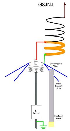
One other idea I'm currently trying, is to add a helical winding for 80m, but fed from the wire connecting the two copper tubes together. This point is at low impdedance, and should match the 80m winding fairly well. However the bandwidth may be limited, and the interaction between the helical winding and vertical wire may be unpredictable, but I think it's worth experimenting with.
Update - John, G4IJD, has tried this, but we jointly concluded that the very slight improvement that may result is not worth the effort required to implement it. An additional horizontal top wire seems to be the way to go.
